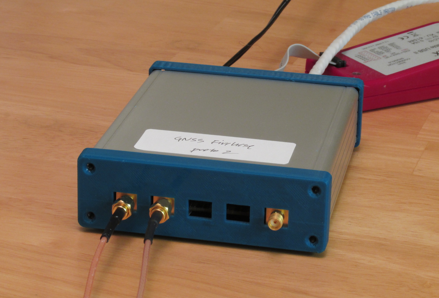
Just a quick update on the GNSS Firehose digitizer project. I've decided to get a few systems professionally assembled; they will be similar to this prototype unit:
Here is some sample data, a sky recording taken on May 6 at around 13:38 UTC:
This represents 10.2 seconds of data simultaneously sampled on bands centered at ~1584.8 MHz and ~1227.7 MHz; each channel has a useful bandwidth of about 50 MHz. The format is raw Ethernet packets as written by tcpdump. The packet2wav utility unpacks the various sample streams from these packets and checks timestamps.
To use this file with my software receiver, here's a command to acquire all the GPS L1 C/A signals in view:
$ <gnss-3.dat packet2wav | ./acquire-gps-l1.py /dev/stdin 69984000 -9334875
prn   1 doppler  3200.0 metric  3.45 code_offset  863.2
prn   2 doppler  1800.0 metric  1.45 code_offset  603.4
prn   3 doppler  4200.0 metric  2.33 code_offset  456.6
prn   4 doppler  1000.0 metric 10.23 code_offset  134.4
prn   5 doppler -3600.0 metric  1.54 code_offset   57.2
prn   6 doppler -4800.0 metric  1.46 code_offset  433.3
prn   7 doppler  -800.0 metric  1.45 code_offset  222.5
prn   8 doppler  3000.0 metric  1.46 code_offset  488.3
prn   9 doppler   400.0 metric  1.57 code_offset  362.4
prn  10 doppler  3400.0 metric  1.54 code_offset  506.3
prn  11 doppler  1000.0 metric  7.62 code_offset  728.8
prn  12 doppler  -400.0 metric  1.46 code_offset   93.4
prn  13 doppler -2600.0 metric  1.44 code_offset  595.4
prn  14 doppler  -800.0 metric  7.23 code_offset  558.5
prn  15 doppler  -600.0 metric  1.51 code_offset   90.7
prn  16 doppler     0.0 metric  1.43 code_offset  772.2
prn  17 doppler  3200.0 metric  1.44 code_offset  301.7
prn  18 doppler -1200.0 metric  2.20 code_offset  760.5
prn  19 doppler -1600.0 metric  1.59 code_offset  657.4
prn  20 doppler -4400.0 metric  1.50 code_offset  910.4
prn  21 doppler  2200.0 metric  1.42 code_offset  674.6
prn  22 doppler  -800.0 metric  6.54 code_offset  923.6
prn  23 doppler  4200.0 metric  2.08 code_offset   94.4
prn  24 doppler  2200.0 metric  1.55 code_offset  406.4
prn  25 doppler  3000.0 metric  4.29 code_offset  513.2
prn  26 doppler  1600.0 metric  1.47 code_offset  628.4
prn  27 doppler   600.0 metric  1.51 code_offset  135.4
prn  28 doppler   200.0 metric  1.45 code_offset  631.4
prn  29 doppler  1600.0 metric  1.47 code_offset  378.4
prn  30 doppler -2800.0 metric  1.52 code_offset  737.5
prn  31 doppler  3000.0 metric  6.61 code_offset  367.1
prn  32 doppler  2600.0 metric  5.98 code_offset  176.8
prn 133 doppler  1600.0 metric  3.20 code_offset  481.3
prn 135 doppler  1400.0 metric  3.82 code_offset   86.7
prn 138 doppler  1400.0 metric  2.67 code_offset  824.9
$
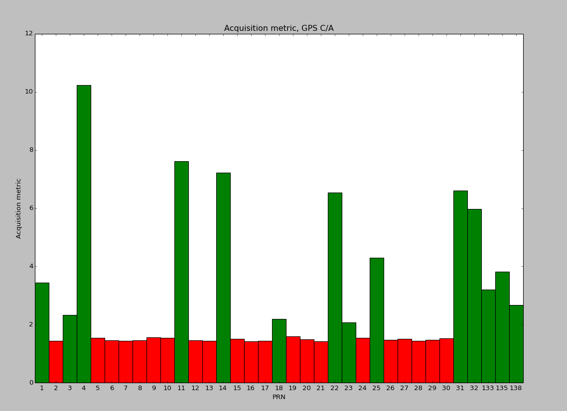
A plot of these acquisition metrics across the various PRNs:
Here's a summary of the visible signals on L1 after acquisition is done across all the GNSS services:
GPS L1 C/A:      1 3 4 11 14 18 22 23 25 31 32 133 135 138
GLONASS L1 C/A:  (none found)
Galileo E1b:     14
Galileo E1c:     14
BeiDou B1I:      11 14
and on L2:
GPS L2CM:        1 3 25 31
GLONASS L2 C/A:  -2 -1 3 5 6
GLONASS L3I:     (none found)
GLONASS L3Q:     (none found)
Galileo E5bI:    14
Galileo E5bQ:    14
BeiDou B2I:      11 14
My L1/L2 antenna, an AeroAntenna AT2775-42, doesn't quite cover GLONASS on L1. Occasionally a signal on channels -7 or -6 is strong enough to show up, but no luck for this capture. GLONASS L2 is fine though, as are the newer GLONASS L3 CDMA signals (not present in this capture unfortunately). Of course other signals such as L2CL and P will be acquirable and trackable as well, but they are more difficult to acquire blindly.
Just for fun, here are the raw samples from the L1 channel. Clearly not much can be seen from this, but it can be useful as a quick check. Samples are 2 bits (represented on the output stream as two's-complement 8-bit for processing convenience), alternating I and Q, at 69.984 Msa/s.
$ <gnss-3.dat packet2wav | od -Ad -tx1 | head
0000000 ff 03 03 03 01 ff fd 01 ff 01 03 01 ff 01 03 fd
0000016 01 fd ff fd ff fd ff ff ff fd ff ff ff 03 ff 01
0000032 01 03 01 03 ff 03 03 03 01 ff ff ff ff 03 01 01
0000048 03 01 01 fd fd 01 01 03 01 01 01 01 03 01 01 03
0000064 fd fd fd ff fd 03 fd ff ff 03 01 ff ff fd fd 01
0000080 ff 01 03 ff ff ff 03 03 03 01 ff ff ff ff 01 ff
0000096 fd 01 ff ff 01 01 ff ff ff fd 03 fd ff fd ff fd
0000112 01 01 fd 01 ff fd ff 01 fd ff ff ff 01 01 ff ff
0000128 01 01 01 01 ff 01 03 01 03 ff 01 ff 01 01 01 01
0000144 01 fd fd 01 ff 01 01 ff 01 03 ff 01 01 03 01 01
And the raw samples from channel 2, the downconverter channel looking at L2:
$ <gnss-3.dat packet2wav 2 | od -Ad -tx1 | head
0000000 ff 01 fd 01 01 01 01 ff ff ff fd 01 ff 03 01 03
0000016 03 01 fd 01 fd ff ff 01 ff 03 fd 03 fd ff ff 01
0000032 03 ff 01 fd ff fd 01 01 ff 01 fd 01 01 fd ff ff
0000048 ff 01 03 ff 01 fd 01 ff 01 ff 03 ff ff ff ff ff
0000064 ff ff 01 fd 03 01 03 ff 01 fd ff 01 ff ff fd 01
0000080 ff 01 01 ff 03 01 01 03 03 01 01 ff ff ff 03 ff
0000096 ff ff 01 ff 01 ff 01 01 03 01 01 fd ff fd ff ff
0000112 fd 03 ff 01 ff ff 03 ff 01 ff fd 01 01 fd 01 fd
0000128 01 fd ff ff ff fd fd fd 01 01 01 03 ff 03 01 03
0000144 ff 01 ff 01 01 01 01 ff 03 01 01 ff ff ff ff fd
I plan to add the FPGA and software support for the third RF channel (set to cover L5 by default) over the next few weeks while the boards are being manufactured and assembled. I now have a simple helical antenna suitable for L5, so I should be able to do tri-band experiments.
Pointers to the GitHub repositories containing hardware design and software receiver:


